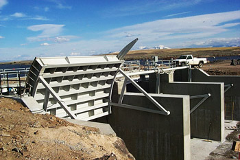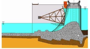
Radial Gates, also known as tainter gates (after the structural engineer who popularized them) are the most common type of spillway gate in use today. It is classified as an undershot gate because water flows under the gate. It consists of a curved skin plate supported by a structural steel frame. A hoist system is used to raise or lower the gate.
Advantages
- Better discharge characteristics than partial gate openings.
- Low cost.
- Bearings are located out of the water.
- Aesthetics – Does not require an overhead supporting structure (gate tower).
- Does not require gate slots which can become plugged with ice or debris and can cause cavitation.
Disadvantages
- Longer piers.
- Relatively high concentrated loads at the trunnions.
- More complex fabrication than other gate options.
- More complicated dogging system to facilitate maintenance activities.
Parts
Radial gates consist of the following four parts:
- The gate leaf assembly, including the curved skin plate, cross bracing or struts, supporting beams and girders, and rubber seals.
- Arm assembly, including the arm columns, bracing, and hub.
- Trunnion assembly, including a pin, busing, thrust washers, lubrication provisions, and yoke.
- Trunnion support assembly, including the trunnion beam or anchor block and anchorage system.
- Wire rope hoist system.
 Structural Design
In a radial gate, water pressure is transferred from the curved face to the radial gate arms which transfer the load to a common bearing on either side of the gate opening.
Load combinations for water control gates can be complex and special care should be taken in identifying all of the important combinations. Agencies will usually provide guidance (or rigid codes) on this but I will present here some of the most important ones:
- Dead Load + Impact (during installation, dry testing, or servicing)
- Dead Load + wave load
- Dead Load + Hydrostatic Load corresponding to top of gate
- Dead Load + Hydrostatic Load at design flow level + Ice load
- Dead Load + Hydrostatic Load at spillway design flow (gates open)
- Dead Load + Hydrostatic Load at design flow level + Earthquake force
- Dead Load + Hydrostatic Load at Inflow Design Flow with gates open.
Hydraulic Design
Hydraulically, the gate is a sluice gate and should be designed as such. You use the Bernoulli equation to equate the energy on both sides of the gate, which eventually results in:
v1(b1·h1) = v2(b2·h2)
Where:
v1 = upstream velocity (m/s or ft/s)
A1 = upstream flow area (m2 or ft2)
b1 = upstream flow width (m or ft)
h1 = upstream flow height (m or ft)
v2 = downstream velocity (m/s or ft/s)
A2 = downstream flow area (m2 or ft2)
b2 = downstream flow width (m or ft)
h2 = downstream flow height (m or ft)
This results in the downstream flow depth and velocity (b2 and h2), which you would use in the spillway or canal design.
